Kill the Plywood Nail Board.
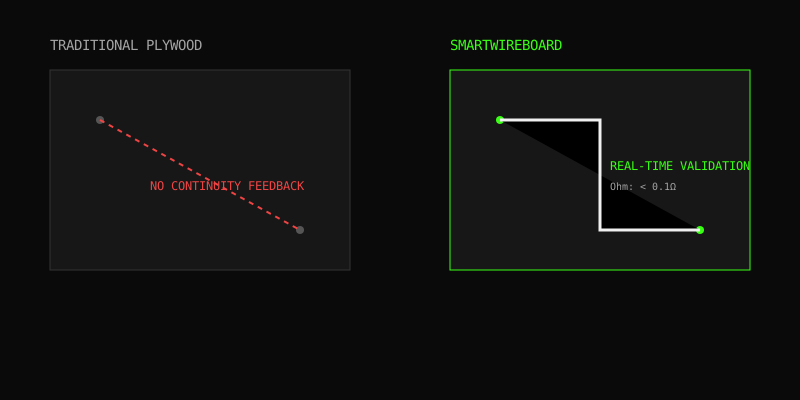
Prototyping a wire harness on dead wood guarantees routing errors, pinout inversions, and blind continuity faults until final test. SmartWireBoard replaces the nail board with active logic nodes that validate every connection in real-time as you route.
SYSTEM METRICS // BARE METAL

The Cost of Blind Prototyping
In standard automotive and aerospace harness prototyping, manufacturers rely on 1:1 scale drawings glued to plywood, with nails driven in to guide wire bundles. This method is passive. It cannot tell the operator if Pin 4 was mistakenly routed to Pin 7 until the harness is fully taped, removed from the board, and placed on a continuity tester.
A single pinout error discovered post-taping requires destroying the harness covering to correct, costing an average of $350 in rework time per complex harness (Source: IEEE Harness Manufacturing Analysis).
SmartWireBoard embeds logic at every node. As the operator routes the wire, the board confirms the connection instantly via LED and API.
The Active Routing Stack
01. Node Deployment
Instead of nails, place Smart Nodes at branch points and connector terminals on our conductive grid base. Magnetically locking, structurally rigid.
Deployment Guide →02. Digital Netlist Sync
Upload your Capital, E3.series, or generic CSV netlist. The board knows where every wire must originate and terminate before routing begins.
Netlist Specs →03. Real-Time Feedback
Touch the wire to the source node, touch to destination. Immediate visual confirmation (Green/Red) directly on the board.
Continuity Logic →Physical Reality
Grid Base Tiles
24" x 24" Anodized Aluminum with embedded FR4 power/data planes. Daisy-chain up to 50ft via CAN bus.
Smart Nodes
Magnetic locking mechanism. 50N sheer force resistance. Embedded RGB LED for routing state.
Terminal Interfaces
Gold-plated pogo pins. Supports 26 AWG to 2/0 AWG via interchangeable collets.
Environmental
IP54 rated against dust and shop debris. Operating temp: -10C to +50C.
Data Agnostic Ingestion
SmartWireBoard does not require you to abandon your existing CAD software. The system controller parses standard comma-separated netlists exported from any major suite.
- Siemens Capital (Standard XML / CSV)
- Zuken E3.series (Custom Scripts)
- AutoCAD Electrical (From/To Lists)
- Legacy Excel Spreadsheets
System Tolerances & Limits
| Parameter | Min Value | Max Value | Constraint Note |
|---|---|---|---|
| DC Continuity Resistance | 0.1 Ω | 5.0 Ω | Programmable threshold via API. |
| Daisy-Chain Board Count | 1 (2'x2') | 25 (50'x2') | Requires repeater injection every 5 boards. |
| Max Active Nodes per Bus | 2 | 1024 | CAN FD bandwidth limited above 1024. |
| Power Draw (Standby) | -- | 12W per tile | 24V DC input required. |
Harness Engineering Tools
Client-side calculators for moving from CAD to physical reality. No server round-trips.
The Operator Experience
SmartWireBoard is designed for the factory floor, not just the engineering office. Operators wearing gloves, managing heavy spools of wire, and dealing with poor lighting need immediate, unambiguous feedback.
When an operator connects Wire A from Node 1 to Node 2:
- Node 2 reads the continuity request.
- The system checks the loaded netlist.
- If valid: Node 2 flashes Solid Green.
- If invalid: Node 2 flashes Strobe Red, and the board sounds a 75dB alert.
The error is caught and corrected in under 3 seconds.
VALID ROUTE ACQUIRED
Real Estate Economics of Prototyping
A secondary, often overlooked advantage of modular active grids is floor space recuperation.
The Plywood Graveyard
A medium-sized harness shop building 30 distinct SKUs must store 30 distinct plywood boards. At an average size of 4x8 feet, this requires massive vertical racking systems, consuming premium factory floor square footage that generates zero revenue.
The Grid Stack
SmartWireBoard tiles disassemble and stack flat. A shop can build 30 distinct SKUs using the same set of 12 tiles. The entire prototyping hardware footprint collapses into a single 24x24x36 inch storage cart when not in use.
Assuming industrial real estate at $12/sqft, reclaiming 1,500 sqft of board storage pays for a base SmartWireBoard system in 8 months.
PLAY DEMONSTRATION: CONTINUITY FAULT ALERT [01:45]
Modular Extensibility
The system grows with your requirements. Add specialized nodes for complex assemblies.
| Module Type | Function | Interface |
|---|---|---|
| High-Voltage Node | Tests EV cable runs up to 1000V DC. | CAN Bus / Isolated |
| Fiber Optic Node | Verifies light transmission and dB loss. | Optical / CAN Bus |
| Impedance Node | Checks twisted pair twist-rates via capacitance. | CAN Bus / RF |
Retire the Nails.
Every day spent routing on plywood is a day risking a $15,000 in-field failure due to a preventable pinout inversion.
Deployment Timeline
- Day 1: Grid setup and firmware initialization.
- Day 2: Netlist integration and parsing trials.
- Day 3: Operator training on node placement.
- Day 4: First live prototype run with zero post-test errors.
Architectural FAQ
Immutable Build Logs
Every connection made on the SmartWireBoard is logged with a timestamp, node ID, and measured resistance. When the prototype is completed, the controller generates a cryptographically signed CSV log.
This allows aerospace quality assurance teams to verify that the physical prototype was routed entirely without DC faults, satisfying initial phase documentation requirements before the harness moves to high-voltage hipot testing.
REST API Automation
Integrate the physical prototyping board directly into your MES or factory dashboard. The local controller exposes an unauthenticated JSON API for querying board state.
Tier-1 Aerospace Supplier
A primary fuselage wiring supplier transitioned from 40 static plywood boards to a single 30-foot SmartWireBoard array in Q3 2023.
- Floor Space Reclaimed: 2,200 sqft
- Scrap Rate Reduction: 14% -> 0.2%
- ROI Timeline: 4.5 months
Ship Hardware Faster.
Stop finding routing errors at the final testing station. Push logic to the prototyping phase and validate physical assemblies in real-time.
Request a Configuration Quote